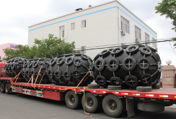
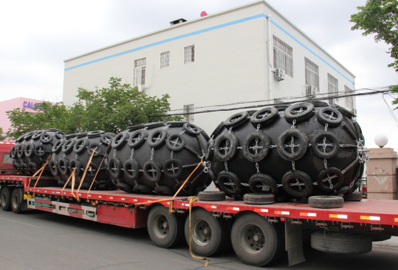
Safety And Reliable Boat Protection Yokohama Rubber Fenders
Advantage of Yokohama Rubber Fender
1. Safety and Reliability
Boat Rubber Fender are constructed of several layers of strong tire-cord, and are thus resistant to pressure and cutting. The safety factor adopted in the design of this fender is based on accepted theory and has been proven by extensive experimentation. large-size fenders are equipped with a safety valve to release the inside air in the event of accidental over-pressure.
2. No Deterioration or Variation in Performance
Boat Rubber Fender utilize the compressive elasticity of air, therefore performance deterioration due to fatigue is absent.
3. Advantages at Inclined Berthing
Boat Rubber Fender, energy absorption does not decrease at inclined compression up to 15 degrees.
4. Most Cost Competitive System
The utilization of the compressive elasticity of air provides completely uniform surface pressure on contact, making Boat Rubber Fender ideal. The surface pressure of the Boat Rubber Fender is equal to the internal air pressure. Due to low and uniform surface pressure properties, the Henger Pneumatic Rubber Fenders are popular at LNG-ship terminals.
5. Soft Reaction Force for Ship and Jetty Structure
The reaction force of Henger Pneumatic Rubber Fenders does not increase sharply, even under excess load conditions. Therefore, the Boat Rubber Fender perform well in such cases, and protect ships and mooring facilities.
6. Lower Mooring Forces under Rough Weather Conditions
The reaction force and deflection of Boat Rubber Fender do not easily reach the maximum because the reaction force increases slowly and allowable deflection is wide. Thus, the Henger Pneumatic Rubber Fenders safely protect ships and mooring facilities even under rough weather.
Specificaton of Yokohama Rubber Fender
| Size |
Initial Internal Pressure 50kPa |
Initial Internal Pressure 50kPa |
|
Diameter/
Meter
|
Length
/Meter
|
Energy Absorption /KJ |
Reaction Force /KN |
Energy Absorption /KJ |
Reaction Force /KN |
| 0.5 |
1 |
6 |
64 |
8 |
85 |
| 0.7 |
1.5 |
17 |
137 |
24 |
180 |
| 1.0 |
1.5 |
32 |
182 |
45 |
239 |
| 1.0 |
2.0 |
45 |
257 |
63 |
338 |
| 1.2 |
2.0 |
63 |
297 |
88 |
390 |
| 1.5 |
3.0 |
153 |
579 |
214 |
761 |
| 1.7 |
3.0 |
191 |
639 |
267 |
840 |
| 2.0 |
3.5 |
308 |
875 |
430 |
1150 |
| 2.5 |
4.0 |
663 |
1381 |
925 |
1815 |
| 2.5 |
5.5 |
943 |
2019 |
1317 |
2653 |
| 3.0 |
5.0 |
1050 |
2000 |
1571 |
2709 |
| 3.0 |
6.0 |
1312 |
2488 |
1888 |
3292 |
| 3.3 |
4.5 |
1175 |
1884 |
1640 |
2476 |
| 3.3 |
6.0 |
1675 |
2783 |
2338 |
3652 |
| 3.3 |
6.5 |
1814 |
3015 |
2532 |
3961 |
Features of Yokohama Rubber Fender
1. Yokohama rubber fenders shall consist of a cylindrical air bag with hemispherical heads at both ends, which shall be filled with compressed air. The basic body construction of this fender shall consist of an outer rubber, synthetic-tyre-cord layer (see Annex A) for reinforcement, and an inner rubber. All of these shall be vulcanized firmly.
2. The outer rubber shall protect the cord layers and inner rubber from abrasion and other external forces. This rubber compound shall have sufficient tensile and tear resistance strength to withstand anticipated weather conditions and severe usage.
3. The inner rubber layer shall seal the air inside.
4. The reinforcement synthetic-tyre-cord layers shall be strong enough to hold the internal pressure. In both compressed and non-compressed situations.
5. The flange opening shall be at either end, or both ends, for convenience of air charge and water filling for Type I and Type II. The flange opening shall be at only one end for Type I Single and no metal parts shall be at the other end to make that end safe from permanent deformation when it gets over compression.
6. The end of the reinforcement-cord layers shall enter the bead ring and be turned up outside the bead ring, which is built-in at the flange opening. Diameter of the bead ring or other steel material around the flange opening shall be less than 0,20 D (D: fender diameter) to make metal parts safe from permanent deformation when it gets over compression near to 80 %. For Type I (Net-type) fenders, the bead ring, and turning up on construction can be excluded.
7. Fenders of diameter 2 500 mm and larger shall be equipped with a safety valve for releasing excess internal pressure when the fenders are over-compressed accidentally. Fenders which are smaller than 2 500 mm in diameter, can be equipped with a safety valve if required.
8. The fender shall be equipped with an air valve for inflation and checking air pressure.
Outer and Inner Rubber Material Requirements of Yokohama Rubber Fenders
|
Test item
|
Test method
|
Required value |
| Outer rubber |
Inner rubber |
| 1. Before aging |
– |
– |
– |
| 1.1 Tensile strength |
ISO 37:2011 |
18 MPa or more |
10 MPa or more |
| 1.2 Elongation |
ISO 37:2011 |
400 % or more |
400 % or more |
| 1.3 Hardness |
ISO 7619-1:2010 |
60 ± 10 (Durometer hardness
Type A)
|
50 ± 10 (Durometer hardness
Type A)
|
|
2. After aging
|
ISO 188:2011
|
Air oven aging, 70°C ± 1°C,
96 h
|
Air oven aging, 70°C ± 1°C,
96 h
|
| 2.1 Tensile strength |
ISO 37:2011 |
Not less than 80 % of the original
property
|
Not less than 80 % of the origi-
nal property
|
| 2.2 Elongation |
ISO 37:2011 |
Not less than 80 % of the original
property
|
Not less than 80 % of the origi-
nal property
|
| 2.3 Hardness |
ISO 7619-1:2010 |
Not to exceed the original prop-
erty by more than 8
|
Not to exceed the original prop-
erty by more than 8
|
| 3. Tear |
ISO 34-1:2010 |
400 N/cm or more |
No requirement |
| 4. Compression set |
ISO 815-1:2008 |
30 %(70 ± 1 °C, 22hours) or less |
No requirement |
|
5. Static ozone aging
test
|
ISO 1431-1:2012
|
No cracks after elongation by 20 % and exposure to 50 pphma at 40 °C for 96 h |
No requirement
|
|
NOTE If the colour of the outer cover is not black, the material requirements will differ from those in this table.
a Parts of ozone per hundred million of air by volume.
|


 Your message must be between 20-3,000 characters!
 Please check your E-mail!
  Your message must be between 20-3,000 characters!
 Please check your E-mail!


